
Modifying A Naim CD5i:i:si For Dual Power Supplies
However, the CD5i (being the baby of the brand) is the only Naim that is not upgradeable at all. It doesn't even have a 'digital out' port. Which means that if you want to go along the "standard" upgrade path, you'll have to do some DIY. That is what this mod is designed to do. The existing toroid inside the CD5i will be modded to power only the CD Transport and Digital section whilst the new additional toroid will power the Analogue section alone. This is only possible because when you open up one of the *Cap power supply boxes, you usually find a single toroid and small circuit board with lots of empty space everywhere else. That means that you really only need space for a toroidal transformer and the CD5i is a player that has just enough to squeeze one in there.
Now Naim's use nuvotem toroids and this mod will use a similar one. It is available from RS Electronics with the part number 223-8061 and it is a 160VA toroid with 2x12V secondaries (each rated at 6.66666A max).
Before I go any further:
MAINS TRANSFORMERS CAN KILL YOU. VERY VERY HIGH VOLTAGES ARE GENERATED INTERNALLY. I ACCEPT NO RESPONSIBILITY IF YOU DECIDE TO FIDDLE AND END UP FRYING YOURSELF OR YOUR KIT. FURTHERMORE, THIS MOD INVOLVES DRILLING A HOLE IN THE BASEPLATE OF THE CD PLAYER WHICH WILL INVALIDATE YOUR WARRANTY. ONLY PROCEED IF YOU'RE HAPPY WITH THIS AND ARE HANDY WITH A SOLDERING IRON.
YOU HAVE BEEN WARNED !
N.B. Many people have done this mod with step-by-step instructions on various forums. There is even a company in Europe willing to do it for you at a price, so it isn't a new idea at all. I have added my own technical detail, explanatory notes and slight modifications.
Also note that the CD5i (Philips transport & Bitstream DAC) that I used to own evolved into the CD5i (Philips transport & Wolfson DAC) which then evolved into the current CD5si (custom Naim transport & Burr Brown DAC) which I now use... for the purposes of this tutorial I will refer to the CD5i but this mod can be used identically on all 3.
The Naim CD5i Internal FlatCap Mod
Tools Required
Drill with 6mm drill bitSoldering iron, flux and rosin
Philips screwdriver to remove the metal base of the CDP
IC/VReg heatsinks & thermal paste
Tie wraps
2A, 250V slow blow 5x20mm glass fuse
Potting Compund - optional
Procedures
Stage 1 - sending all OEM power to the digital section: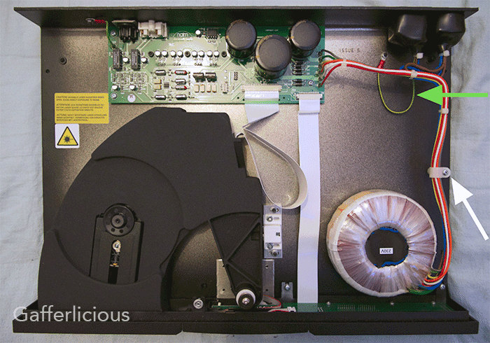
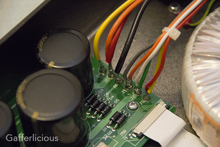
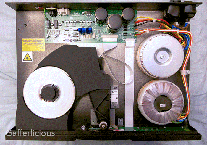
After opening the CDP, first move the Earth wire (green arrow above) out of the way and then remove the cable clip (white arrow above). This will give you the room needed to fit the new transformer.
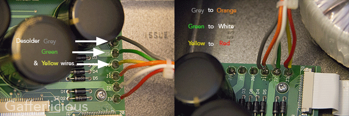
Unsolder the grey, green and yellow wires from the right side of the pcb and solder them to the three existing transformer connections as follows:
- grey to orange
- green to white
- yellow to red
Stage 2 - adding new power to the analogue section:
Now place the new transformer into the case but do not fix in place (you may need to move it around when making connections).
Snip off the OEM cable tie at the rocker switch and pull the shroud down then thread the blue and brown wires (the primary) from the new toroid through the shroud. This is a tight fit and is best done by using some slim grips/pliers to pull them through one by one. They should fit snugly without the need to cut the shroud at all. Solder the new wires in place using the uppermost two pins. This is important because the electricity passes from the power cord via the bottom two pins, through the switch, out the topmost two pins and on to the OEM toroid. Therefore if you soldered onto the bottom two pins, you would in effect bypass the switch and cause the new toroid to be powered on all the time. Solder blue to blue and brown to brown before replacing the shroud.
Now solder the new secondaries in place:
- yellow to J4
- orange and red to J5
- black to J6
Stage 3 - securing the new power supply to the case:
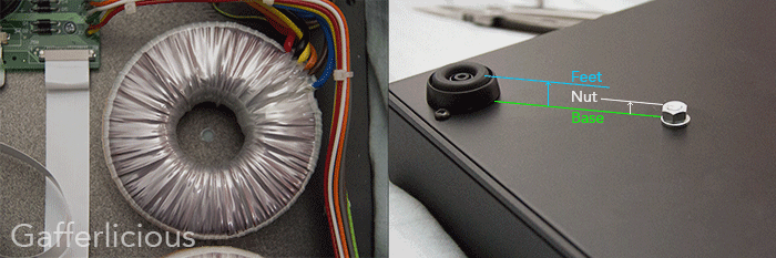
Mark the best transformer position by using a pen through the centre hole to mark the case. Now carefully drill a 6mm hole through the lower case in the marked position. Slide the insulating pad beneath the transformer and insert the top insulator, clamp plate and bolt. Fit the retaining nut to the bottom of the case and tighten "finger tight". As you can see from the picture, the bolt doesn't protrude too far below the casing so it won't interfere with how the player sits on the shelf.
Stage 4 (optional) - potting the transformer:
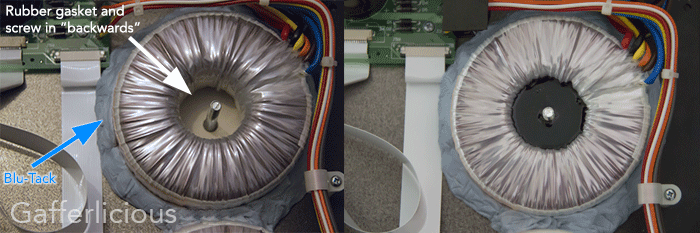
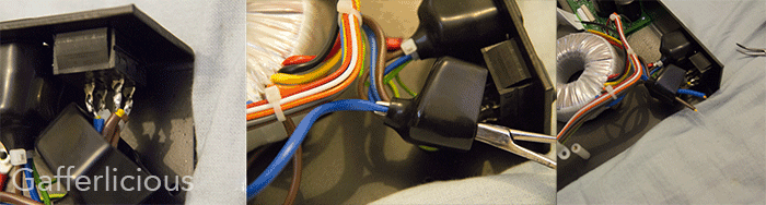
You may find that the new toroid hums quite loudly (as all toroids do). To reduce this somewhat, you could additionally pot the transformer. Potting is simply covering the coils with a damping material that wicks away the heat (high thermal conductivity) without compromising the electrical flow (low electrical conductivity) all whilst damping the vibrations from the windings to reduce the hum. The potting compound itself is a type of epoxy resin made from mixing two liquids together and costs about £7 for the amount you need. To prepare the toroid for potting, simply reverse the screw so that the 'common' screw head is now outside the chassis and assemble as above but without the upper rubber gasket, plate or washer/nut. Now add Blu-Tack around the bottom edge of the toroid as potting epoxy is quite a thin liquid initially and you don't want it leaking out around the base. You'll end up with the picture above left in preparation for the compound. Now, fill the "well" that's left with the epoxy potting resin (about 100g should do) and leave to set. Once cured, add the last remaining items and tighten (don't forget to remove all the Blu-Tack too).
Stage 5 - cooling the voltage regulators:
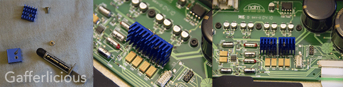
The analogue section's voltage regulators were stepping down the 12V supply to 9V...a difference of only 3V so they wouldn't get too hot. However, with the new power supply they are stepping a bigger combined (2x12V) down to 9V so they may get very hot. This excess heat needs to be dissipated so it is a good idea to add some heatsinks to those regulators. Rather than glue or stick the heatsinks on, it is better to align and mark them, then drill a new hole into them in order to screw them to the regulators (alternatively buy pre-drilled heatsinks designed specifically for regulators). Make sure you add a little thermal paste to the mating surfaces beforehand to ensure good heat transfer as shown in the leftmost picture. Once screwed on, there's plenty of space for them to radiate heat safely but I bent them back a bit to move them slightly further from the CD tray. In use they're great, really heating up nicely and quickly meaning they're successfully transferring heat away from the voltage regulators as intended.
Stage 6 - protecting against inrush current:
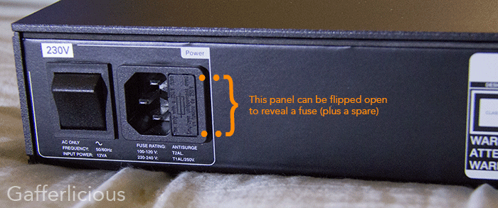
Inrush current is a phenomenon peculiar to transformers and worse in toroid transformers. What happens is that on 'switch on', a large current draw occurs whilst the transformer stabilises (only for the first few seconds). This can be 15x higher than the operating current of the transformer so a fuse is needed to cope with this initial surge. Naim use Littelfuse slow blow fuses of 1A for the single toroid CD5i. As I am now using two similar toroids, I changed the fuse at the IEC power inlet terminal to 2A, as without this, that fuse kept blowing on switch on.
There are a few extras worth mentioning here. Firstly, if you find that despite having the correctly rated (2A, 250V, slow blow) fuse it keeps blowing, it's usually because it is of inferior quality to the OEM Littelfuse offering (which is more expensive but worth it in the long run). Secondly, another thing that can prevent blown fuses is to switch on the equipment quickly rather than slowly (I have no idea why this works, but it does).
Stage 7 - the finishing touches:
Carefully dress the wires as neatly as possible ensuring that the blue and brown wires leading to the rocker switch are at least 10mm from the edge of the base to prevent the top cover catching them. Tie wrap as needed to make it neat and remember to replace the cable clip you removed at the beginning.
Double and triple check all wiring has been correctly soldered and all colours match the tutorial PRECISELY. Now plug in and turn on to check it all works. Once done, fully tighten the retaining bolt and refit the cover.
So What's Happened To The Power?
The OEM Naim toroid is a 120VA Nuvotem that is wired to run in series and has double outputs in order to run 2 circuits (analogue & digital). In this "mode", you could use a single 24V tap or use as centre-referenced earth to get a 12-0-12 twin configuration. This will provide 5A on each leg as this simplified diagram shows: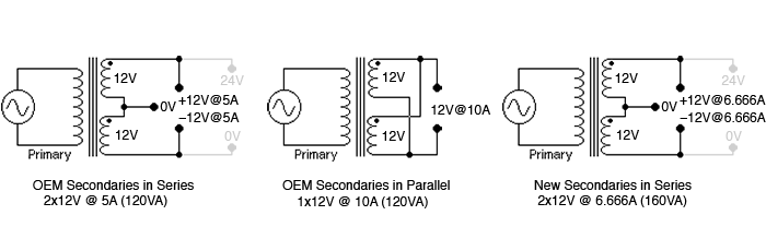
By changing to a parallel config, I can double the available current to 10A whilst the new toroid can provide 6.666A in series - both more than the 5A each side got before:
OEM            Digital/Transport: 12V, 5A   (60W)      Analogue Section:   12V, 5A      (60W)     Total Weight: 5.7kg
Dual Power     Digital/Transport: 12V, 10A  (120W)     Analogue Section: 2x12V, 6.666A  (2x80W)   Total Weight: 7.3kg
...and the Sound?
It's no surprise to learn that the change in sound is similar to adding a FlatCap to a CD5x seeing as this is doing the exact same thing. The soundstage is larger whilst retaining imaging and the bass is slightly deeper at the expense of a little PR&T. It's quite subtle but definitely noticeable. Best of all, it doesn't cost £795 but is instead a measly £27 and about half an hours work.
However, the biggest reason for me doing this is that I like the logical idea of providing a better power supply to the components. By having power supplied to the delicate analogue section and separately to the less delicate digital and transport sections, I should get cleaner power with less noise and interference. More importantly, the standard CD5i player has both sections deriving power from a single source, so if one section requires more power whilst the other is drawing it, then it's effectively limited in supply. This mod removes that by giving each section it's own clean power supply.
