Servicing The VAL (aka AVC) EL34 Integrated Amplifier
In a tube circuit that uses FIXED-BIAS (whilst producing music, the bias is fixed), the grid-bias voltage is supplied from a power source external to the circuit, sometimes using a battery but usually (more conveniantly) getting it from the transformer itself by insertion of a resistor (Rk) in the cathode lead. The polarity of the voltage developed across this cathode resistor is negative to the grid so the grid itself is receiving its -ve bias from it. This is altered via a trim-pot thereby altering the level of -ve DC a.k.a. bias to the grid. Note that the trim-pots are used to alter the bias when being "serviced"...the bias does not get continually altered whilst the amp is making music in normal use, so it is still a fixed-bias amp. The cathode is grounded so it is sometimes called a COMMON CATHODE circuit.
2 other types of amps use forms of SELF-BIAS (i.e. they bias themselves whilst operating): The first self-bias type is called CATHODE BIASING (such as used in a triode circuit for instance). In these circuits, grid voltage is kept at ground potential and the cathode is made to go positive relative to the grid. The effect of this is the same as making the grid negative relative to the cathode. This method is called cathode biasing because the biasing resistor is in the cathode leg of the circuit. Also, the grid is grounded in these circuits, so it is also called a COMMON GRID circuit. These circuits are used for triode valves and produce less power than fixed bias circuits.
The second self-bias type is called GRIDLEAK BIASING, which makes use of a portion of the input cycle to -ve bias the grid. As a result, this is also known as a cathode follower. With pentodes, the screen bypass g3 must be connected to the cathode and the anode is grounded. Sometimes called a COMMON ANODE circuit.
Without going into too much detail, basically the AVC amplifier has a -ve DC voltage (bias) applied to Grid 1, and it is this that is altered via the trim pots. Therefore it is an ajustable fixed bias (common cathode) Class AB amplifier actually giving ~35Wpc. It is NOT a non-adjustable fixed-bias amp, it is NOT Class A, it is NOT 40 Wpc.
Before I go any further:
VALVE AMPLIFIERS CAN KILL YOU. VERY VERY HIGH VOLTAGES ARE GENERATED INTERNALLY. I ACCEPT NO RESPONSIBILITY IF YOU DECIDE TO FIDDLE AND END UP FRYING YOURSELF. IF YOU DO NOT UNDERSTAND WHAT I HAVE MENTIONED SO FAR ANYWAY, THEN IT'S PROBABLY BEST YOU LEAVE BIASING TO A TECHNICIAN.
YOU HAVE BEEN WARNED !
N.B. This is version 3 of "how to bias a valve amp". My original version 1 relied on you buying a quad of precisely matched tubes, but you've got to remember that even the best matching in the world isn't perfect. As a result along came version 2 which took into account the fact that you won't need to specifically match all 4 valves and is therefore a slightly more "robust" approach to correct biasing. The current version 3 adds more technical detail and explanatory notes.
Biasing Your Valves v3.00
Tools Required
Digital multimeterLong-handled slotted screwdriver
Philips screwdriver to remove the metal base of the amp
Basic Calculations
The anode voltage in this amp is 470V.An EL34 can produce 25W (so 2 per channel gives 50W maximum).
Biasing changes the Plate Dissipation which in turn determines how much power the valve produces. To run in true class A configuration as claimed, you would need to run the valves at 100% plate dissipation, but these are actually set from factory for 75% dissipation and run as class AB amplifiers.
Plate Dissipation = (Bias Current x Anode Voltage) / Tube Power
From this, we can plug in the numbers and see that AVC sets the bias current at 40mA to get that 75% (0.75 = 0.04 x 470 / 25), but this runs the valves very hot resulting in more power but much shorter life. To get slightly more reliability and longevity, we can set the bias current to 39mA instead to get a plate dissipation of 73%, or run slightly cooler for even longer life at 38mA to get 71% (anything 70-75% will sound pretty similar and give about 35Wpc).
V = I R
The resistors the current runs through in the circuit are 10Ω and for the purposes of this tutorial, I will be biasing at 39mA.
So typing these into the calculation means that we want a meter reading of 39m x 10 = 390mV DC.
Procedures
- Make sure the power switch is in the OFF position and THE VOLUME IS TURNED ALL THE WAY DOWN.
- Install all the tubes to the corresponding sockets using a gentle rocking motion.
- Connect your speaker leads, input cable and power cord.
- Turn the Amp upside down and remove the base. Turn the amplifier ON.
- LEAVE TO WARM UP FOR 30 MINUTES.
- Turn on the multimeter. Select the section for measuring up to DC 2000mV.
- Attach and secure the negative test lead to the chassis or to a -ve binding post.
- Now insert the positive test lead onto the EL34 base IN THE V1 TUBE SOCKET (pin1 is the Grid 3 point that is soldered to the 10Ω resistor see the red arrow in the picture below).
- Carefully insert a long-handled slotted screwdriver into the bias adjustment pot corresponding to the EL34 tube socket you're on (see the purple arrow in the picture below).
- Slowly rotate the screwdriver to adjust the bias voltage until it reads '390' on the multimeter (which means 0.39V on the setting we have it on).
- Repeat for all remaining EL34 tubes.
- You will need to return a few times until all four tubes are properly biased (there is some interaction, so re-adjustments back and forth may be needed before the voltages are all the same).
- Once you have finished biasing all four EL34 tubes, wait a few minutes and recheck the settings again.
- At this point, if a valve(s) continues to drift, it probably needs replacing - large amounts of drift is the sign of a bad tube, small amounts the sign of mains variations.
- You have now biased your amp. Switch it off and CAREFULLY screw the base plate back on and turn over (it's HOT). Relax and Enjoy!
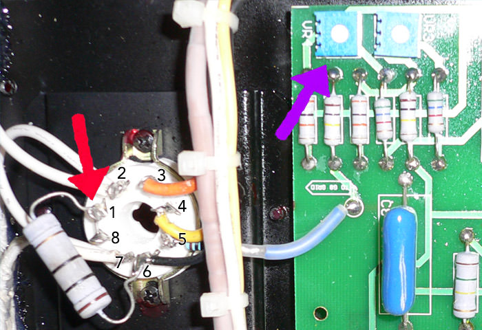
A more precise method would be to measure the exact resistances of each of the resistors beforehand and calculating the individual voltages required for each of them to give 39mA....however, this is probably wasted here, where the resistors are only accurate to within tolerances of up to 10% anyway (if you do want to do this, measure the resistances beforehand when the amp is still switched off - the procedure is otherwise the same).
Valves are EL34 power tubes (6CA7 are worse quality). I think the
Pre-amp section is GE JAN 5670, which are 2C51 valves. The WE NOS 396A is the best version of this, the 6N3(P) are worse quality. Pre-amp valves do not need to be biased.
If you follow the above procedure, you do not need to go back to specific/unreliable end-sellers for tubes but can order 4 pre-amp tubes and 4 EL34's from the net and bias the amp correctly yourself (which will allow you to try other makes of EL34/5670 and experience the different sounds on offer from different manufacturers). Just make sure you order similar type tubes specifying they'll be used in a common cathode Class AB, -ve fixed-bias amp and "micro-adjust" the amp as necessary following the above....DON'T ELECTROCUTE YOURSELF.
Upgrading the Resistors
OK, so whilst biasing, I realised that one of the resistors wasn't quite showing 10Ω and the valve there was drifting quite a bit. This is because the resistors are good but not the best quality in the AVC amp. They are rated at 5W power (with max up to 700W) and built to a tolerance of 10%, meaning that they could actually be anything from 9Ω to 11Ω and still be 'within spec'. I decided to upgrade them to 10Ω resistors rated at 10W power (with max up to 1000W) and built to within a tolerance of 5%: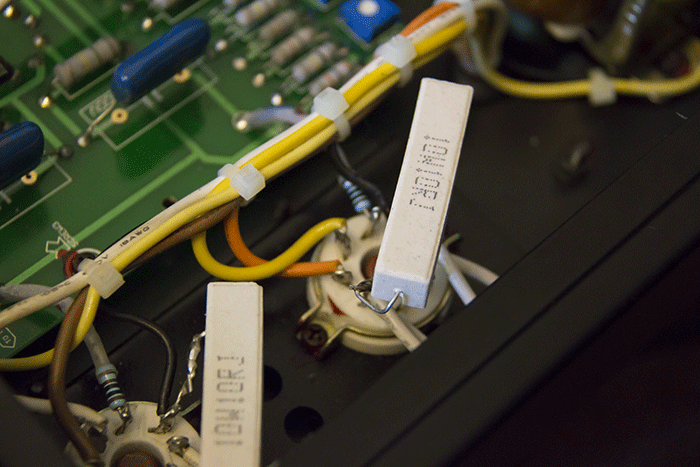
As you can see, they are about twice as big as the OEM ones but it was still extremely straight forward to solder them into place instead. I'm happy because now they have less chance of failing and causing issues with my new EL34s.
Fixing the Volume Knob
The volume knob was the next thing to fix. It is meant to be an ALPS 100K logarithmic potentiometer with click stops. Unfortunately, the clicks had stopped and there was an awful screeching in both channels whenever I tried to change volume. I was considering soldering in a new ALPS Blue Velvet replacement but then thought I'd try some DeoxIT instead. A variable potentiometer is simply a contact that slides around a carbon plate. Over time, the contacts oxidise and deposits build up inside, resulting in a poor current flow between them hence the screeching sounds.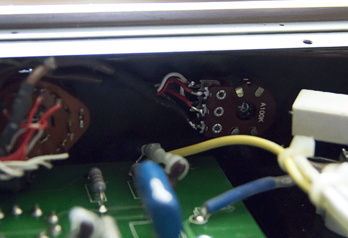
All I did was to apply 2 one second bursts of DeoxIT into the pot in order to de-oxidise it internally. I then swivelled the volume pot around a bit to spread the solution and et voila, good as new. Even the click stops had reappeared. Finally, I sprayed a small amount of WD40 in there as well in order to lubricate and protect it. Result? It sounds and feels as good as new and I don't need to replace it (DeoxIT is expensive but I would highly recommend it - I also used it on the trim pots for the valves).
Why persevere with a Valve Amp when Solid State is ubiquitous now?
Why do all the above when I can have newer technology solid state? Simple answer, valve amps sound better....much better. The reason there is more availability and variety of solid state amps is because valve amps tend to receive a negative press from those at the start of the Dunning-Kruger curveDistortion
Solid state amps do have less distortion across their range (typically <0.5%) than valve amps and many people quote high figures when pushing an amp hard. However, valve amps tend to be better at delivering voltage and usually don't need to be cranked up to be enjoyed (the average listening level at max volume before it becomes uncomfortably loud is actually <10Watts whatever amp you use). At these levels a valve amp is easily able to deliver low distortion (my Prologue gives about 0.4% at my loudest listening level). If you are deaf/mad enough to listen at maximum volumes, valves amps are also safer as they distort evenly which has much less chance of damaging a speaker's voice coil than the clipping you otherwise get with transistor based amps (solid state).Treble
It is a myth that valve amps always have a "rolled off" treble by default. There are many valve amps that sound very bright as well as those that have a smoother more balanced sound and my valve amp has no treble roll off when measured with a calibrated mic (yet still sounds clear and non-fatiguing with all genres).Bass
Another myth peddled is that transistor amps have better bass - my valve amp gives amazing bass slam because the bass has nothing to do with the valves. It has everything to do with the transformers. Big, heavy duty, custom wound transformers (expensive and therefore supplied with higher end equipment) will provide a low end that's easily more than a match for even the best solid state designs.Soundstage
This is where a valve amp outshines anything transistor based. What most folk refer to as "3D sound" is actually a massively improved soundstage in width and height as well as depth. This means you can get an effect where you feel you can actually walk amongst the band laid out in front of you, around the singer, between the instruments, 1" away from the drums etc. The massively improved spatial separation as well as focus and imaging is very hard to obtain with transistor amps (and you usually have to spend much more to achieve it). An easy way to explain this is simply to say "grab a vocal track, listen at any volume, close your eyes.....it will sound like the singer is standing in the room in front of you with a well designed valve amp".So where do these ideas come from?
Most people take examples from the biggest market for valve amps which isn't hi-fi, it's guitar amps. Now guitar amps are designed to be driven hard and loud and deliberately to be driven into distortion. As they cannot get the same sound from transistor based amps, valves have stayed. However, this is a completely different scenario and use to home audio valve amps which are used well within their design envelopes. Unfortunately the arguments surrounding live stage use have crossed over into the hi-fi world and so many of these erroneous arguments will crop up again and again and will be bolstered by the poor quality and performance of the many cheaper Chinese based brands available today. Talking of which...
A Word Of Warning about the Affordable Valve Company...
On his train wreck of a website, the owner of AVC seems to have an issue with other better designed/superior valve amps. Just for the record, I own bothThere are a number of advantages to the hand-built PrimaLuna over the cheaply mass produced AVC. Firstly, the PrimaLuna uses ONLY point to point hardwiring in the signal path, unlike the AVC below left which has a large, cheap PCB holding most of the circuitry. Hardwiring in the PrimaLuna below right allows for more mechanically robust contacts and a better signal propagation which all means a vastly improved sound:
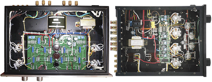
There actually is a circuit board inside the PrimaLuna but this is not in the actual signal path. It is a circuit that allows for continued adjustment of the bias "on-the-fly" (AutoBias) so that the tubes are each running at their own individual optimums. It's far superior to standard fixed-biasing, which is what the AVC uses.
However the most important issue with buying one of the Affordable Valve Company amps is that you are not guaranteed any servicing at all nor any support from the company after you've bought it. I myself bought mine direct from AVC, after which the company owner refused to either service it nor supply me with replacement tubes, despite having invoices and proof of original ownership showing that the amp was bought first hand (it was issues like this that nudged me into researching valve biasing myself and creating this tutorial).
This attitude is worsened if you happen to have bought your amp second hand like many forum users have done, where you will effectively get stonewalled despite requesting to pay for your amps servicing needs (with many people that do pay still never receiving their valves).
Fortunately, if you still want/need aftercare for your amp, and do not wish to do this yourself, the good folk over at
"Unfortunately, when the hurricane hit America, the American computer stopped working" what, all of it?
"How can you tell who is 100% honest, and who is 'bent' ?"
"WARNING = BEWARE OF COUNTERFEIT ITEMS FROM CHINA" ...like the rebranded AVC amp; mass produced in China and rebranded for many companies such as T.A.C.?
"This is not a con to get money out of you"
"Since amplifier was his own stupid fault we told him what we thought of him. Do you think it would be fair to call him a liar and blackmailer?" referring to one of his own customers
"It is strange that some people will listen to what some idiot say on some Internet"
"Think for yourself, THAT IS THE ONLY WAY THAT YOU WILL NOT BE CONNED BY ME"
"We do NOT support second hand amplifier, that you bought from somebody else" there goes your 2nd hand value
"Just compare the size of OUR transformers"
"You MUST buy replacement valves from us" why? you've seen how to adjust bias for them above
"This is not a con to get money out of you"
"I thought about this point, looked at all the safety aspect of how can I design an amplifier" he didn't design it. Looking inside there's nothing special/different about what he sells despite what he claims ...notice the same massive massIVE MASSIVE transformers used in the mass produced V.A.L. VP-100, who supply his amps 'as is'
"The problem is that most "fashionable" gurus do not understand electronics, AND THEY ARE TOO LAZY OR TOO PROUD TO SIT DOWN AND READ A TEXTBOOK"
"Fashionable false guru cannot explain any technical details, BECAUSE THEY DO NOT HAVE A BASIC UNDERSTANDING OF VALVE AMPLIFIERS" why all the shouting?
"We are fed up of idiots who tamper with our amplifiers. WHY THE BLOODY HELL DO YOU WANT TO TAMPER WITH OUR AMPLIFIERS !" see above
"I would like to the valuable America eBay customer for his questions" eh?
"HUGE HUGE HUGE POTTED OUTPUT TRANSFORMERS"
"I hope that the DVD Audio people do not "start creating trouble""
"Please do NOT buy VERY EFFICIENT loudspeakers"
"Make human voices sound bluer, muddle, congested as though thesinger got a flu / cold and blocked up nose"
"Please stop messing about with DIY (Do It Yourself) speakers + buy our GBP £650 speakers"
"This is not a con to get money out of you"
etc etc ......CAVEAT EMPTOR
